Quartz crystal microbalances—or QCMs as they are commonly called—are electronic devices used within vacuum deposition chambers to measure thin film thickness on substrates. They do this by tracking the frequency response of a quartz crystal during the coating process. This frequency change can be related to the amount of coating material on the crystal surface.
The optical, semiconductor, solar cell, and thin film display (OLED) industries, to name a few, use quartz crystal monitoring in their production processes. Quartz crystals monitor thickness at the Ångström level; in everyday terms, 1 Angstrom is equivalent to 0.00000000393701 Inches or 0.0000001 Millimeters. This extreme level of precision accuracy is critical because thickness deviations as little as 10 Angstroms can have a major effect on product performance.
Understanding the importance of this process control system and its limitations is critical for creating innovative and new products. The importance of quartz crystal sensors as a production tool has been steadily increasing in the past twenty years. More advanced optical, electrical, and magnetic devices require a process sensor capable of measuring layer thicknesses with 1 Angstrom resolution reliably. Additionally, many new thin film product manufacturing lines operate continuously, requiring a crystal sensor to not only accurately measure minute differences in thickness, but to do so for very long periods of time.
A quartz crystal microbalance (QCM) or film thickness, monitoring system is comprised of three components: 1) the quartz crystal sensor, 2) a temperature controlled housing, or “sensor head” and 3) an electronic monitor or controller that forces the crystal into vibration and tracks the frequency of this vibration over time. An internal microprocessor then converts this frequency into the actual thickness of the film. Each component has critical operational characteristics: 1) for the crystal: its frequency range, resistance and electrode quality, 2) for the sensor holder: its temperature regulation ability and mechanical integrity, and 3) for the monitor: its ability to track accurately the crystal frequency changes and temperature characteristics.
Quartz crystal monitoring systems are an essential component within thin film deposition vacuum chambers used in mass production. Many thin film products require a highly accurate and repeatable thickness of material deposited on a substrate. For example, commonly deposited materials in the optical industry are TiO₂, SiO₂, MgF₂, and ZnS, to list a few. These thicknesses are often on the order of 1,000 Angstroms or less, and require a layer accuracy of less than 10 Angstroms.
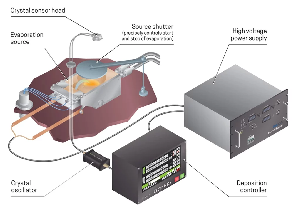
The thickness monitoring system is contained partially within the vacuum chamber and partially outside. The in-vacuum components are 1) the crystal, 2) the sensor head, (with the electrical connection, water lines, thermocouple and heating elements) and 3) the feedthrough, which connects the internal components with the air side. The external components include: 4) cables and fittings from the feedthrough, 5) the oscillator which makes the crystal vibrate and measures this continuously, and 6) the monitor or controller which displays and acts upon this information.
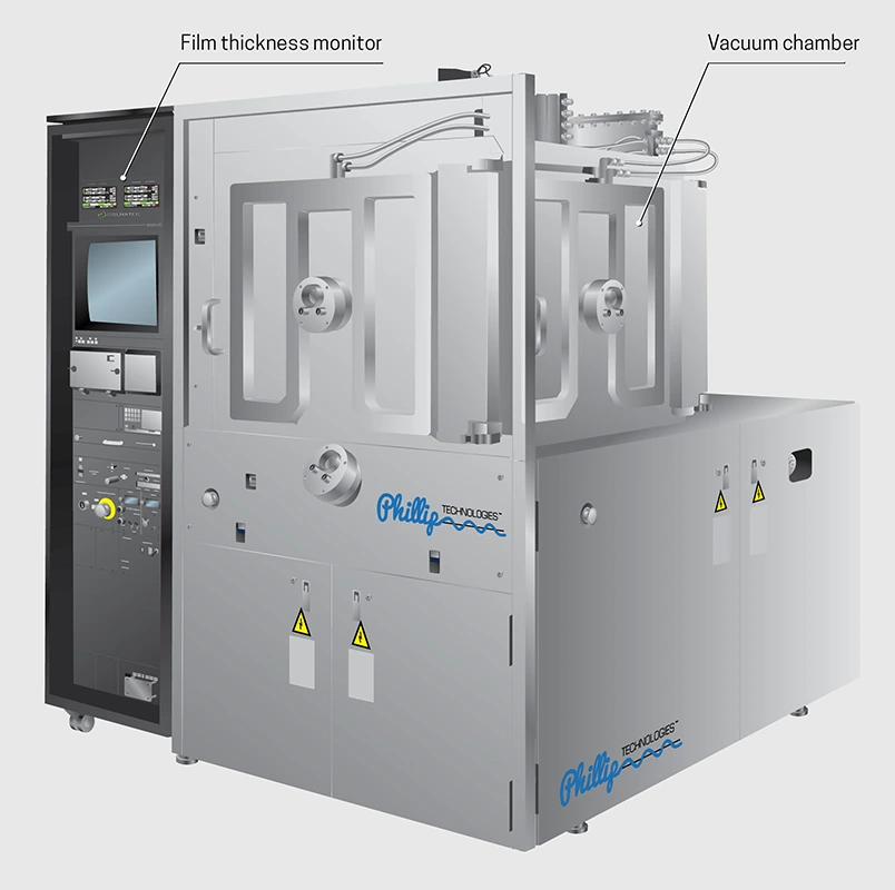
A vessel of varying shapes that creates a vacuum condition nearing that of outer space (10−6 Torr). This vacuum is achieved through the use of a series of vacuum pumps including rotary vane, diffusion, cryogenic, turbo-molecular, ion-pumping, and more. Deposition, or coating, takes place within this chamber where the lack of air allows for high purity coatings.
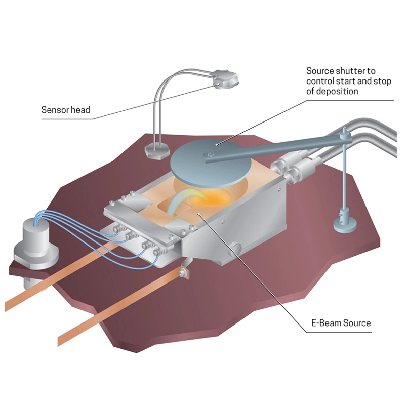
The means for producing vapor used in the coating process. Sources vary in design (thermally resistive boats, electron beam hearths, sputter guns, etc.) and some are better at evaporating different materials than others. Because the position of the source heavily effects the coating distribution or uniformity, these also dictate the chamber shape.
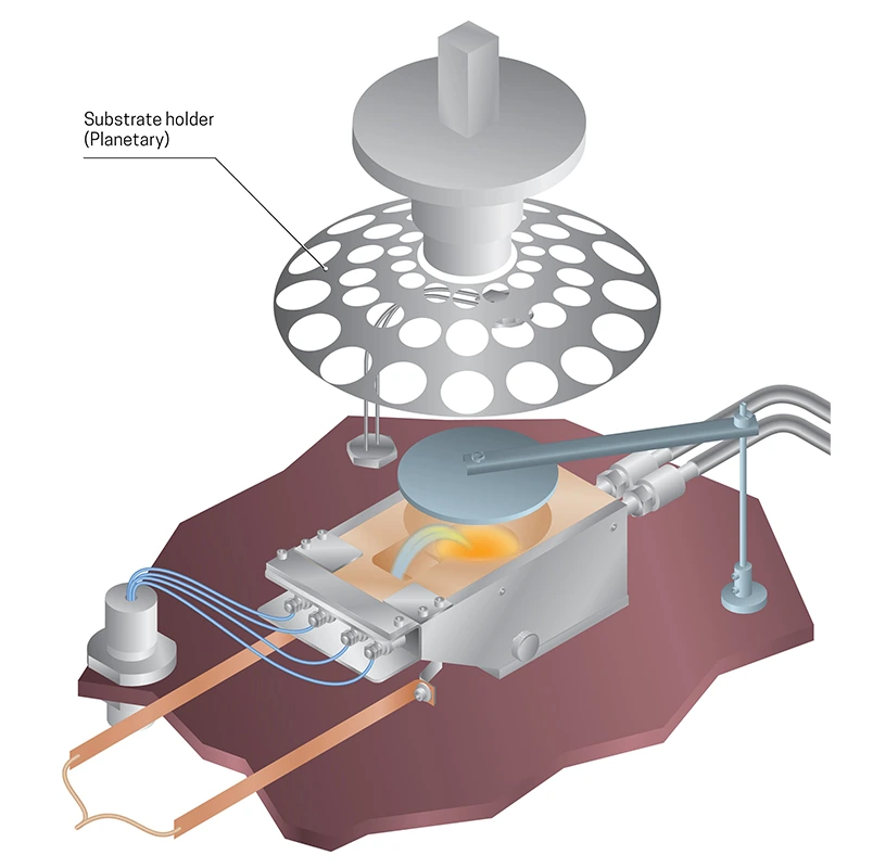
Device or product getting coated. In order to achieve uniform deposition on the substrate surface, special attention must be given to the position and movement of the substrate in relation to the coating source. Substrates are mounted on a holder, called a Planetary, and they must be oriented and frequently moved in precise patterns.
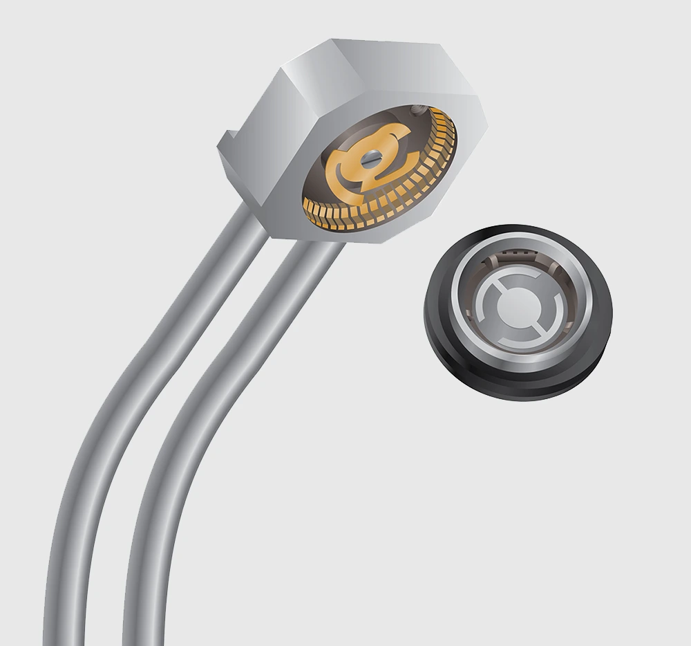
This is the mechanical assembly where the crystal (AT or RC) is placed and electrical contacts connect the crystal to an oscillator. The sensor head contains water or air lines for cooling, a heater for changing he sensor head temperature, and a thermocouple. Crystals are very temperature sensitive and require temperature control at all times. A sensor head must be “demountable,” meaning the crystal assembly must be replaceable. This is accomplished by using a cap, or holder for the crystal itself. This in turn mounts into a sensor body. The sensor body has a center contact spring that pushes against the backside of the crystal cap making an electrical circuit. The body of the sensor is the electrical “ground” or return path. A heating element is often added to the sensor head. Combine with a thermocouple, or temperature measurement device, this allows for the control of the sensor head temperature in real time. There are many advantages to heating a crystal for optics. The major advantage is that a warm crystal (up to 90°C) is much more stable for monitoring dielectric, or insulating materials like MgF2, SiO2, Ti2O5, and related optically transparent compounds. The useable life of a crystal is increased fivefold by operating a crystal at 90 C vs. the traditional 20 C. This is due to elimination of film stress on the crystal. Sensor heads can hold from 1 to 24 crystals depending on the design. The rationale is that when a crystal fails, or stops operating, the process may continue to be monitored without opening the chamber. This ability to overcome crystal failure is critical because many optical films absorb water from the atmosphere and change characteristics (absorbance, reflectance, refractive index, etc.) when exposed to air. If the chamber is opened mid-way through a coating run, the films may rendered defective.
The feedthrough is the metal assembly that connects the sensor head and its electrical and liquid or airlines through the vacuum chamber wall. Generally there are three types:
The oscillator is an electrical circuit that forces the crystal into vibration or “oscillation.” It does this by finding a natural, or resonance, frequency for the crystal, and tracking it as this frequency changes with the addition of coating. Oscillators must be placed close to the feedthrough (within 6-10″) because the crystal connecting cables make up part of the oscillating circuit. If they are too long, they weaken the strength of the vibration and the crystal measurement becomes erratic.
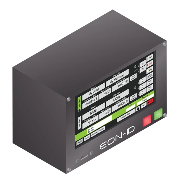
The monitor or controller is a microprocessor based electronic instrument that takes the frequency information from the oscillator, through a coaxial cable, and uses it to calculate the film thickness or rate of thickness being deposited. The algorithm, or formula used, is called the Sauerbrey or modified Sauerbrey equation. This formula relates the mass or weight of the film with the change in resonance frequency of the crystal. As more mass is deposited on the crystal, the vibration slows down. This change can be used to calculate the thickness from the mass. Monitors differ from controllers in that a monitor only measures and displays the thickness or rate change. A controller connects to the deposition source power and adjusts it to match a preset value for rate (which is measured in Angstroms per second). A special consideration must be given to the crystal itself. This is the key component in the entire measurement system. How the crystal is manufactured will affect how well the system works in process control systems.