The following illustrations demonstrate how a traditional AT cut crystal performs during electron beam evaporation (e-beam) and the effects of radiant heat on crystal performance. The same principles outlined here apply to thermal evaporation and other forms of PVD as well.
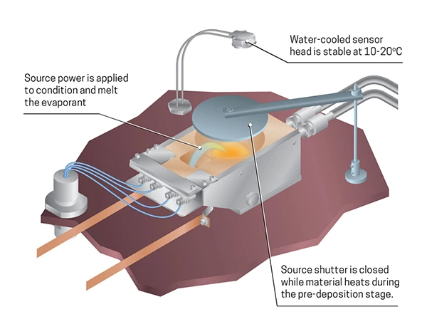
At this stage, the material is being conditioned prior to deposition. It’s at this stage where the sensor head is operating at a stable temperature.
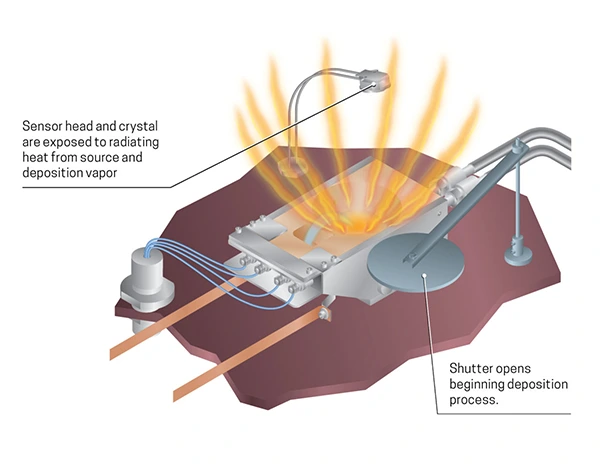
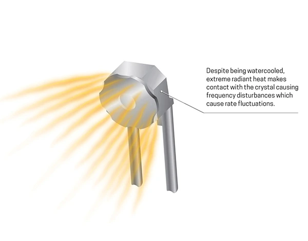
Deposition now begins, flooding the chamber with radiant heat from the evaporation source. The large flux in temperature now presents a severe change in performance.
The sensor crystal is suddenly exposed to an extreme surge in radiant heat that cannot be corrected with the traditional method of water cooling. This heat-stress causes the monitor to react in a detrimental fashion.
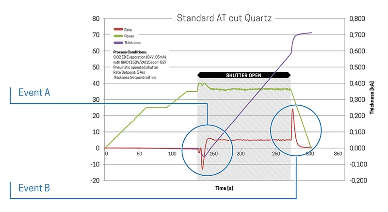
The result of this radiant heat is seen in the process data below. Pay particular attention to the follow events.
Event A: after the shutter opens, the radiation from the source reaches the crystal, the crystal expands, and the frequency rises. This is interpreted by the monitor as negative rate or thickness.
Event B: as the shutter closes, radiation stops and the crystal frequency suddenly decreases because the crystal contracts, leading to a false thickness change. This frequency decrease registers as a rate or thickness increase
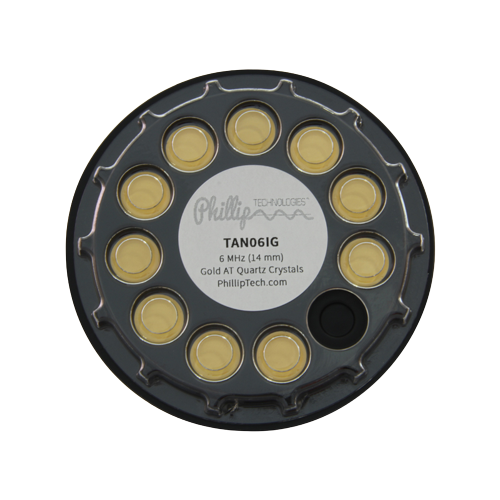
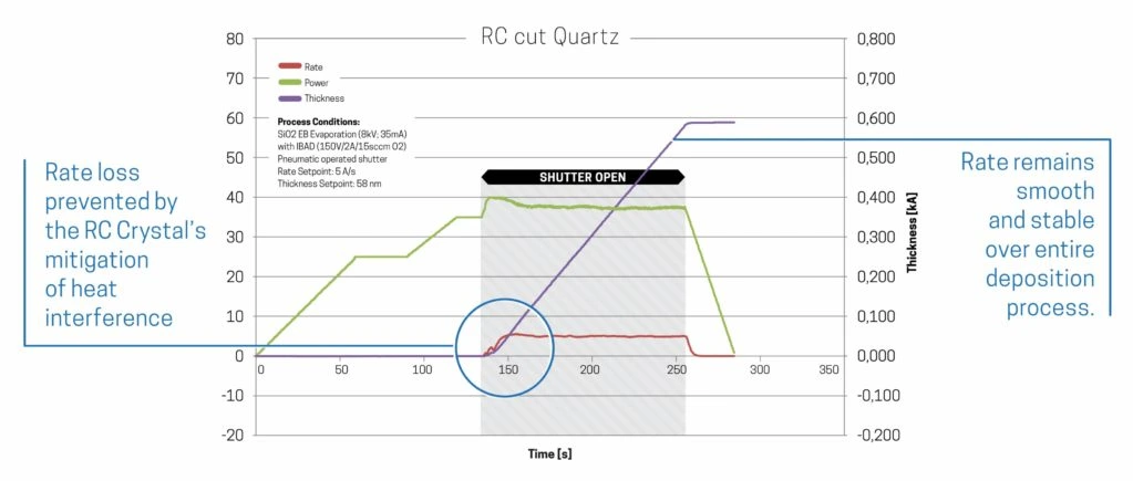
Invented by our CTO, Scott Grimshaw, the RC crystal’s it’s thermal radiation resistance enables the most accurate measurements possible in thin film deposition. RC crystals, mitigate the aforementioned issues because this recently invented design is insensitive to frequency shifts caused by source radiation or film stress. This shift prevention is accomplished by adjusting the stress coefficients of the quartz plate using advanced fabrication methods. The RC crystal will not show a rate spike when the deposition source shutter is opened (Event A). Typically, this action causes a frequency shift of up to 100 Hz, which translates for films such as aluminum, to rate changes of 50 Angstroms. Further, the noise associated with the intense energy of impinging atoms in sputtering is dramatically reduced, owing to the stress insensitivity of the crystal.
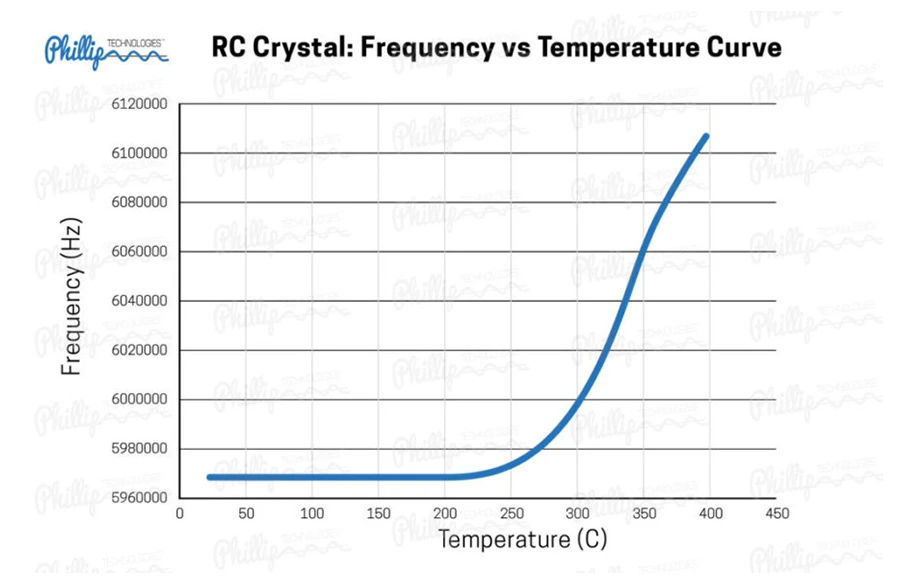
In addition to rate-spike prevention, RC Crystals also can stably operate up to 300°C, which makes them perfect for high temperature applications requiring intense heat, such as ALD, CVD, OVPD, and high temperature PVD. The graph below illustrates the temperature versus frequency turning curve (F vs T) for an RC Crystal.